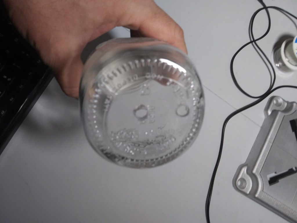
There is a need to improve my ability to work with glass. I found out that you can drill holes in glass using diamond grit hole cutting drill bits. I found some online and a glass bottle to practice on. The important thing here is to do this under water. I heard their is an actual chemical reaction between the glass and the water allowing the cutting to go more smoothly. Here is a video from the Action Lab on Youtube showing that you can actually cut glass with scissors under water
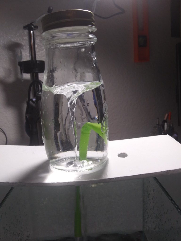
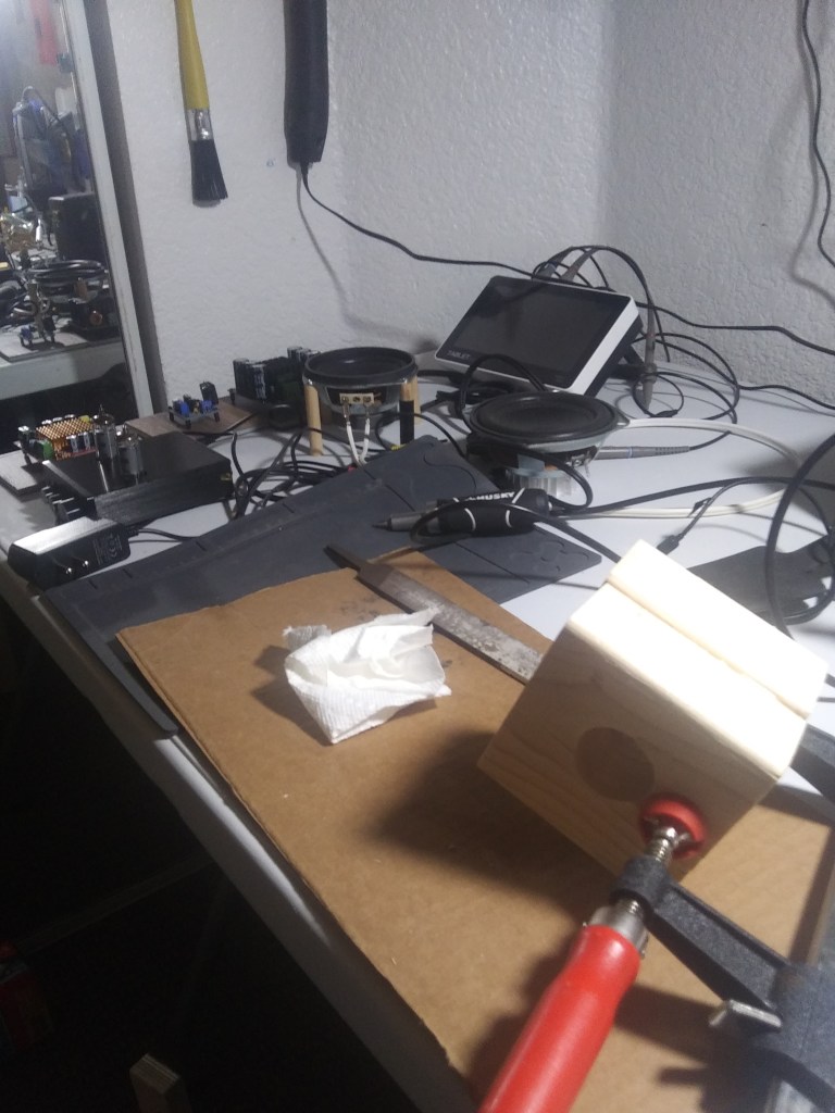
Pretty amazing. So, a quick look at my tools and the resulting vortex I now have with a nicely holed glass bottle.
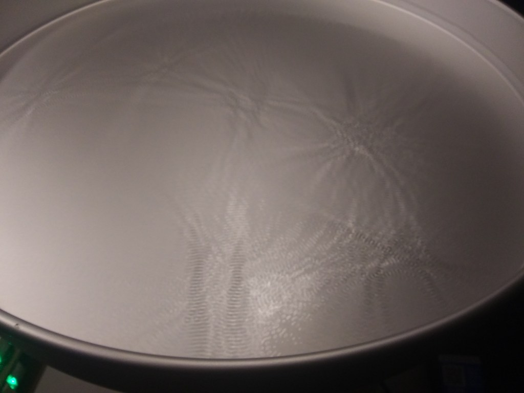
And some cleaner vortex’s
It’s apparent from my experiments that I need to have a way to control the flow of water from the tank. In my next steps, I will buy a pump that is a little bit stronger, also, build a controller using an arduino, resistor pot, and transistor to make an adjustable PWM that will allow me to control the power going to the pump
At this point I want to start controlling the PWM with a more elegant UI. One way to do this is using QT. QML is a IDE/language/designer built with embedded devices in mind. I like QT Quick because it has a well defined separation of view and c-code. QML is very responsive and works with binding, and you can make a beautiful graphical layout including anchors with resizing built in. Their are elements for displaying lists and grids with the capabilities for animation and so much more. I would like to reference the KDAB tutorials as I spent some time to better acquaint myself with the basics. I went through all 50 videos, and continue to look for ways to improve
I started with a basic design, just a slider to control the duty-cycle. I improved it a little, and also used built in features of QT Creator to cross-compile and debug on my Raspberry Pi. This is with the straight forward Raspbian OS, Buster. The updates, upgrades, installation of QT for the libraries, etc… were mostly handled through the apt package handler. Their may have been some configurations that I implemented for static IP and SSH on boot for easier development. These are some basic things for working with Linux. Here are some pics of my simple GUI
As of this point we have an embedded application running on the raspberry pi. I access the application from my laptop (using the shared network and known IP address of the PI), by starting the application from a Putty terminal. On the command line I type
sudo ./QT-PWM_control -platform vnc
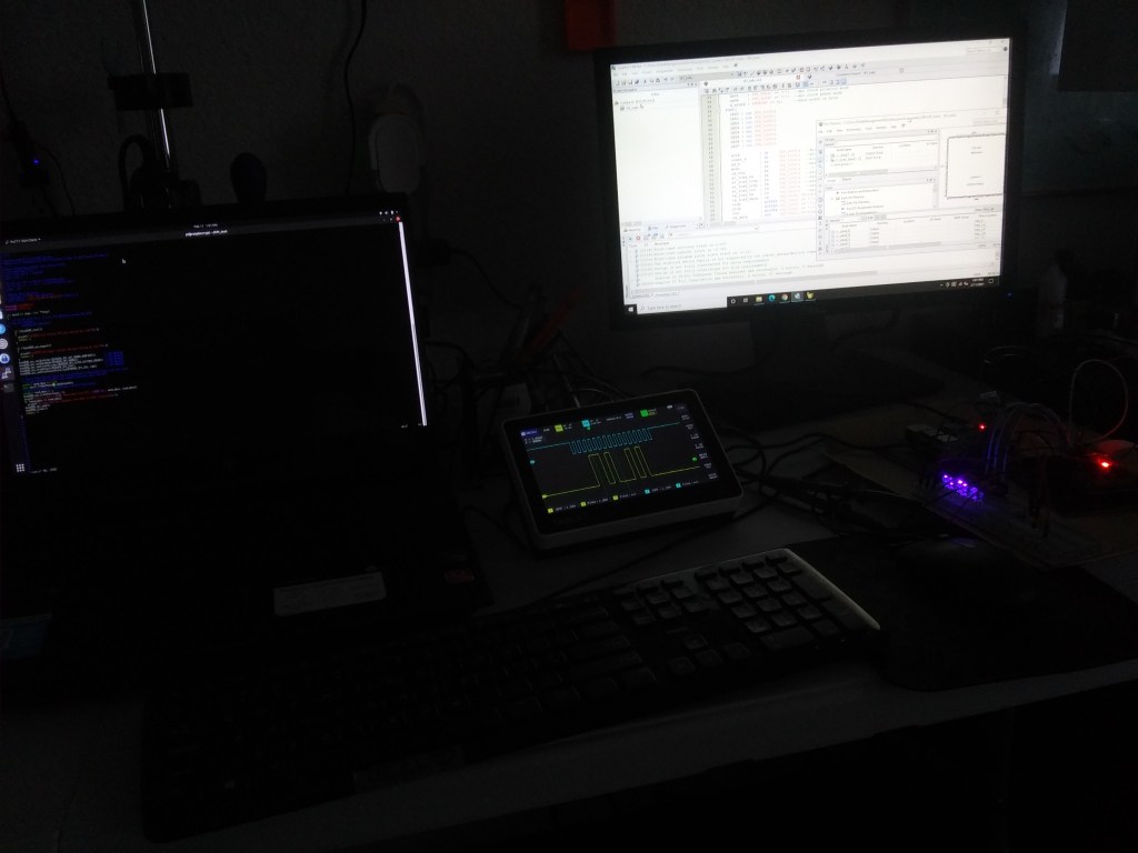
I need to use sudo because the bcm2835.h an library require root access to function. This is how I send my SPI message. I use the -platform vnc because to create the graphical interface on my laptop I need to access a Windows X or graphics connection of some sort. I want to learn more about these types of implementation as I am aware their is like EGLFS which uses more an OpenGL, and I know with HTML a server sends text which is then rendered on a browser. For now, this works. This command opens a port on the Raspberry Pi. I then use TigerVNC, which is a VNC client that can attach to this port (5900 by default). VNC works well, and I am able to push the buttons and see everything fairly quickly as I update the duty cycle which I can see is quickly updated on my oscilloscope.
Having some initial luck learning to program in VHDL, it is time to take on the next challenge. Being able to communicate between our FPGA and a micro-controller is essential to more complex systems where I would actually use an FPGA. I am trying to master this with DMA, so I can store and send registers with data stored in FIFO’s. I am reaching limitations in my ability to debug my code, and in my methods for coding on the FPGA. I have a lot to learn, from better control of clocks with PLL to being able to organize my code better. This is my test bench, using LED’s and an oscilloscope to watch the signals.
To help in learning, I am writing with the Altera group at Intel. Hoping to find guidance on this journey at the forum for developers.
After taking some time to get more familiar with Quartus II for development of FPGA boards using VHDL, I learned to troubleshoot code using the Signal Tap II Logic Analyzer built into the IDE. Now, I can watch any of the pins or signals programmed into the Cyclone II FPGA. It allows me to watch the action while the board is plugged in with the USB-Blaster JTAG debugger. I was able to see the SPI communication from the Raspberry Pi and to watch the user side within VHDL.
Also found to write a more hierarchical code that has a top level, and components so I can coordinate between SPI communications coming in and a PWM output with a duty cycle set by the SPI communication. I use the components as written here
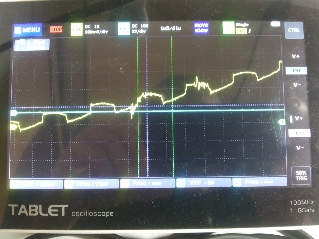
So, at this point, I am able to receive a byte from the SPI that corresponds to the duty cycle I would like to set. I pass that number to the PWM and that is output to a pin that I assign, looking at the Oscilloscope
Now we have a PWM responding to a simple SPI message send from the PI. The Pi is sending via c++ code block, utilizing bcm2835 source.
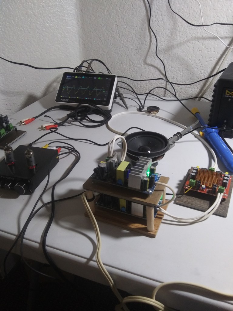
We needed to get more power, so went back and bought a pre-amplifier and a couple new power amplifiers. Also, did some re-wiring, adding proper connectors on the speakers. The results were interesting. actually made the water jump at 174Hz
and, finding the higher frequencies have less visible effects on the water. Even so, I would like to study the effects on mixing liquids, perhaps mixing hydrophobic vs hydrophilic.
And a few photos, looking at the quality of the sound with an oscilloscope connect to the terminals of the speaker. These are signals from my laptop as the source, into a vacuum tube pre-amplifier, into a d-class power amplifier. The D-class amplifier uses a switching mechanism to be more efficient, the A-class amplifier uses analog methods producing more heat but high quality signals. I have yet to experiment with A-class amplifiers.
For the next rounds, I will get a couple new speakers, which I would also like to try wiring in BTL bridged mode. Also, looking for a better design in stand construction.
So, I have decided to continue further using my windows desktop, still unable to configure the USB blaster on my Ubuntu laptop. I will put my first VHDL code on my github profile.
Here are some images of my first programs. HelloWorld, using the timer and counting up in binary on the FPGA. I am working from this tutorial to light up some LED’s and get an initial feel for the QuartusII IDE. I am needing to use the web edition, vs 13 because it is free and works with the cycloneII chip.
In order to write code for this device, I installed the Quartus II v. 13.0sp1, using the web edition because it is free. I installed this to my Ubuntu 20.04.1 LTS. I am using the 64bit version so, after placing the bin directory in my PATH I have to type quartus –64bit in the terminal. Things are running pretty smooth up to this point.
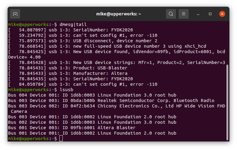
To upload compiled code to the cyclone II FPGA I bought an ALTERA USB Blaster.
This is where I began running into major issues, uploading the code from my Ubuntu machine. To begin, I uploaded everything to my windows machine, including drivers for the USB Blaster. Everything worked out, and I was able to upload the code and these tests prove the device does work. Still, I develop on my linux box so this give me an opportunity to dig deeper into the USB driver.
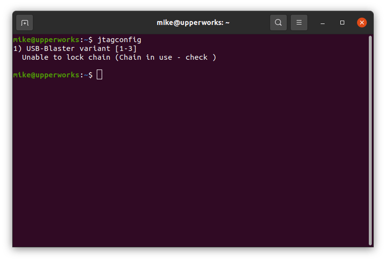
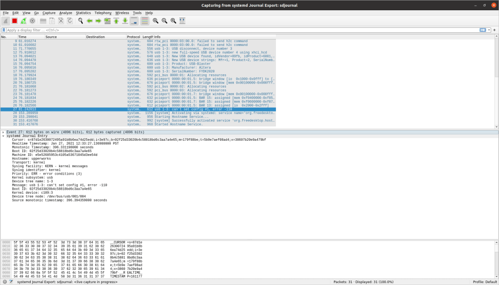
These are some of the error messages I am running up against.
I tried looking on wireshark as well
Going to see if I can use some forums where I can find some help. So far I have written to
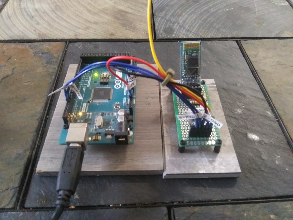
Spent some hours today working on getting the Arduino HC-05 running, and then testing it. I was able to connect the HC-05 through the Arduino to send serial hello world messages to my computer. Using the computer I am able to see the messages with the RFCOMM server through the command line.
I am having a hard time with the QTBluetooth API though, still debugging because the bluetooth socket does not connect, it gets stuck in the connecting status???
We have a ways to go here before having something of value, but further experiments will include our own coil winding to excite crystal activators, and an oscilloscope to observe sound quality in electronic form
Building a way forward to play frequencies through water and see these effects is non-trivial. First you must generate the sound. I have found a command in using Linux to generate pure tones.
padsp signalgen -v -s 88200 sin 396
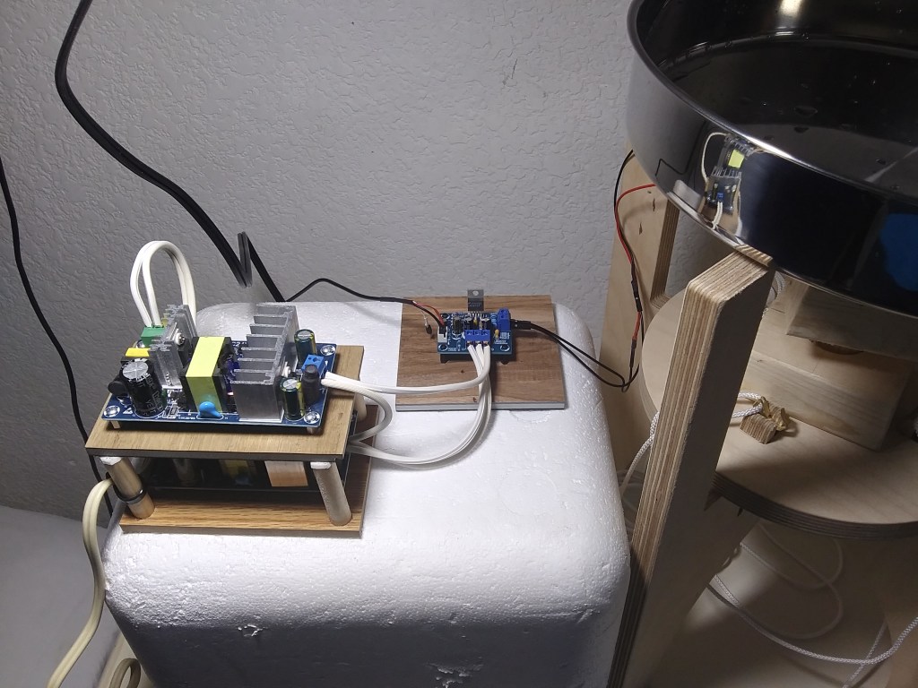
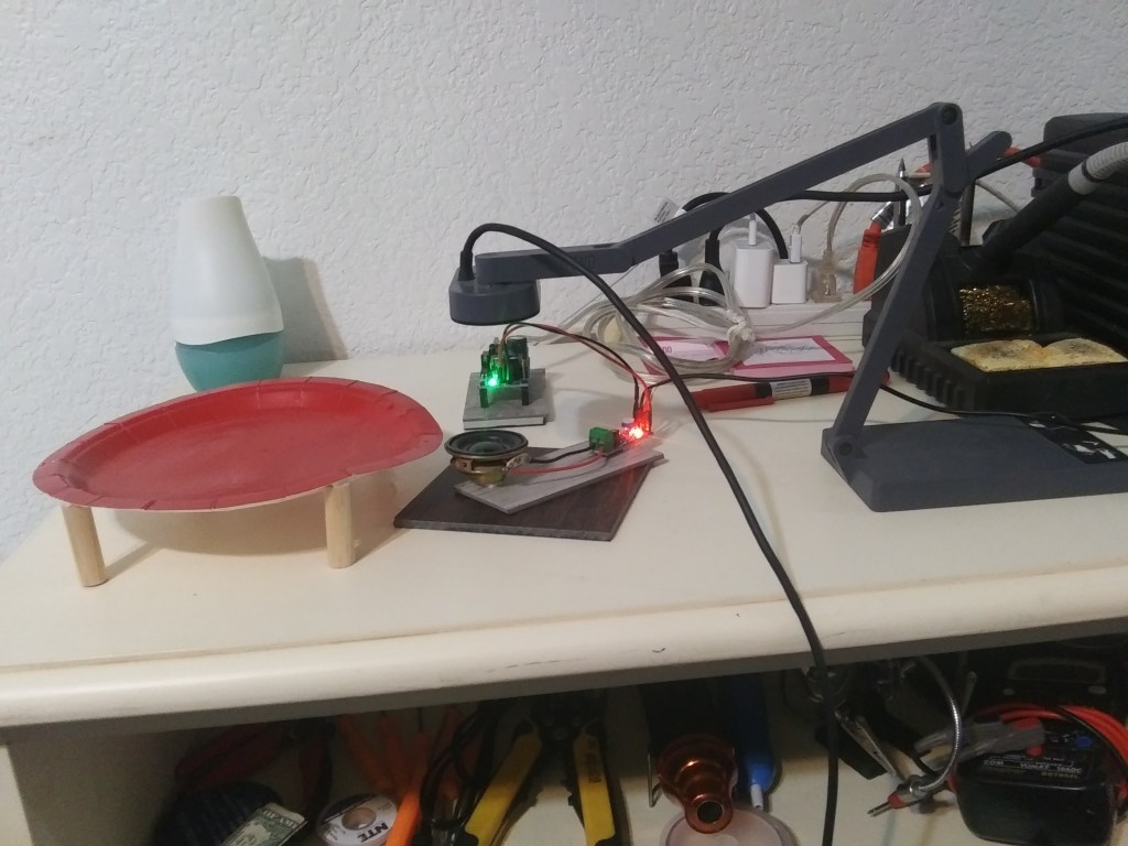
This command generates a 396 Hz frequency, sampled at 88200 Hz. I send this signal to be amplified. I have tried a couple weaker amplifiers but the did not cause much visual effect in the water. From humble beginnings, we sourced our first speakers and materials to experiment with…
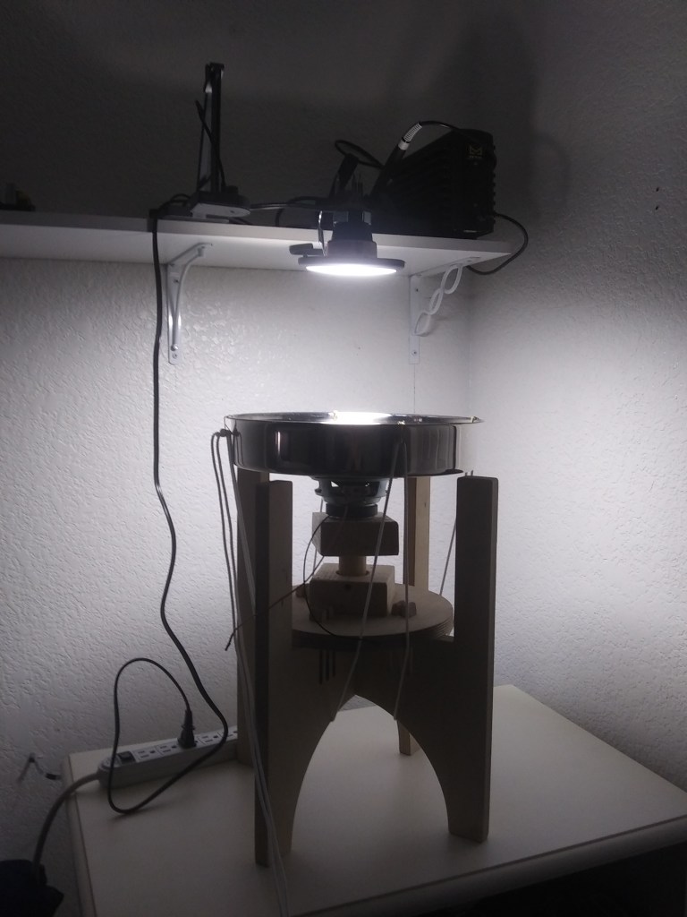
We quickly followed up with a nice stand, some lighting, and a higher quality plate…
You can see we fastened the speaker to the pan, and have now added light to illuminate our videoing of the effects we are working to generate. We also added a mechanism to lift the speak so that it is closer to and in contact with the holding pan.
At this point I am wanting to learn about making my own custom circuits. I know already how to design and make Gerber files to order online, but lead time is a minumum of a few days. Thinking ahead that I want to learn new things and do more prototyping faster; I decide to etch my first board. I can design and etch a board in less than a day! 🙂
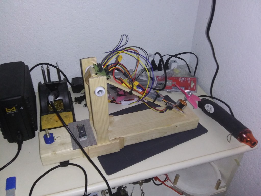
My first board. I messed it up. While exporting the Gerber, switching from PDF to a GIMP file to align the holes in the Drill File. Anyways, did it over again and it works! of course, another uhoh, the propeller spins the wrong direction causing the arm of the test stand to be pushed down instead of up…
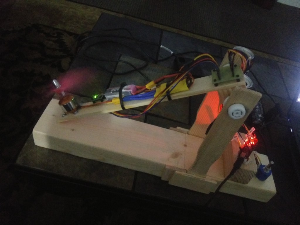
You can change the direction the propeller spins by flipping 2 of the 3 wires in the connector between the XPS and motor. It takes off!!!
I secured the Nano with some extremely small metric screws since then. The next task at hand is to control motor speed with the gyroscope instead of the resistor pot. The goal is to have the propeller speed continually readjust to hold itself level instead of manually controlling speed with the resistor pot.